In this article, we will configure the IPSec Tunnel between Palo Alto and Cisco ASA Firewall. In this example, I’m using PANOS 8.1.10 on the Palo Alto firewall. Although, the configuration is almost the same in other PANOS versions too. A basic understanding of the IPSec VPN will help you to understand this article. You don’t need an additional license on both devices for this feature. You must have a static routable IP address to configure the IPSec tunnel. So, let’s start the configuration!
Scenario – IPSec Tunnel between Cisco ASA and Palo Alto Firewall
As already discussed, you must need static routable IP on both Palo Alto and Cisco ASA firewalls. In this example, I’m using two routable IP addresses on both Palo Alto and Cisco ASA firewalls, which are reachable from each other. IP 1.1.1.1 is configured on the Cisco ASA firewall and 2.2.2.2 is configured on the Palo Alto Firewall as shown below:
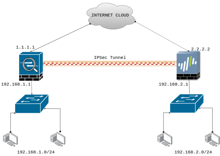
As you noticed, the LAN subnet 192.168.1.0/24 is connected with Cisco ASA and on the other hand, the LAN subnet 192.168.2.0/24 is connected with the Palo Alto Firewall. Before jump into the configuration part, just check the reachability of both devices using the ping utility.
[terminal]admin@PA-220> ping host 1.1.1.1
PING 1.1.1.1 (1.1.1.1) 56(84) bytes of data.
64 bytes from 1.1.1.1: icmp_seq=1 ttl=64 time=0.177 ms
64 bytes from 1.1.1.1: icmp_seq=2 ttl=64 time=0.157 ms[/terminal]
Steps to configure IPSec Tunnel on Palo Alto Firewall
First, we will configure the IPSec Tunnel on Palo Alto Firewall. You need to follow the following steps to configure IPSec Tunnel’s Phase 1 and Phase 2 in Palo Alto.
Creating a Security Zone on Palo Alto Firewall
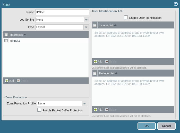
First, we need to create a separate security zone on Palo Alto Firewall. To configure the security zone, you need to go Network >> Zones >> Add. Here, you need to provide the Name of the Security Zone. You can provide any name at your convenience.
Creating a Tunnel Interface on Palo Alto Firewall
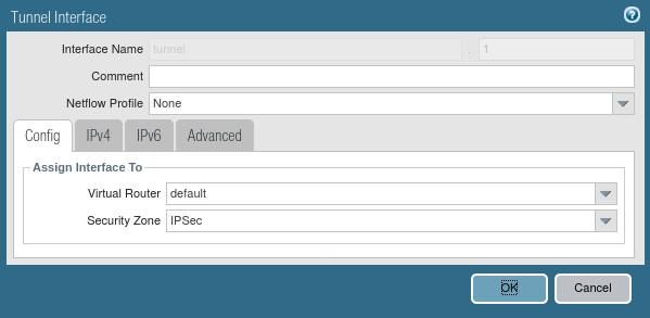
You need to define a separate virtual tunnel interface for IPSec Tunnel. To define the tunnel interface, Go to Network >> Interfaces >> Tunnel. Select the Virtual Router, a default in my case. Also, in the Security Zone field, you need to select the security zone as defined in Step 1. Although, you do not need to provide an IPv4 or IPv6 IP address for this interface. Also, you can attach your Management Profile in Advanced Tab if you need it.
Defining the IKE Crypto Profile [Phase 1 of IPSec Tunnel]
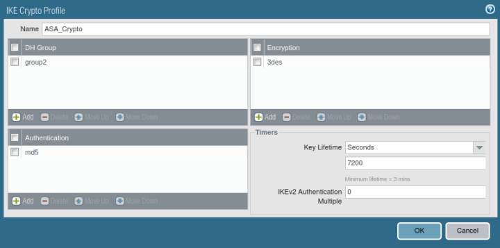
Now, you need to define Phase 1 of the IPSec Tunnel. You need to go Network >> Network Profiles >> IKE Crypto >> Add. Here, you need to give a friendly name for the IKE Crypto profile. Then, define the DH Group, Encryption, and Authentication Method. By default, Key lifetime is 8 Hours. You can change it as per your requirement.
Defining the IPSec Crypto Profile [Phase 2 of IPSec Tunnel]
Now, you need to define Phase 2 of the IPSec Tunnel. You need to go Network >> Network Profiles >> IPSec Crypto >> Add. Here, you need to give a friendly name for the IPSec Crypto profile. Select the IPsec Protocol as per your requirement. You have ESP (Encapsulation Security Protocol) and AH (Authentication Header) protocol for IPSec. Then, define the DH Group, Encryption, and Authentication Method. By default, Key lifetime is 1 Hour. You can change it as per your requirement.
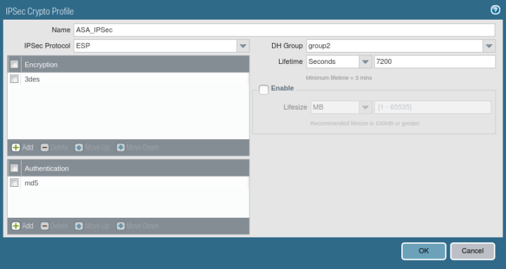
Defining the IKE Gateway Profile
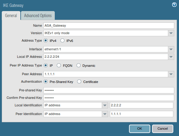
Now, you need to go Network >> Network Profiles >> IKE Gateways >> Add. In General Tab, You need to define the name of the IKE Gateway Profile. In the Interface field, you need to define your Internet-facing Interface, In my case, ethernet 1/1, which has a 2.2.2.2 IP Address. Define the Peer IP Address Type IP. Define the peer address, in my case 1.1.1.1. Select the Authentication Method, i.e. Pre Shared Key or Certificate. In this scenario, I’m using the Pre-shared Key. Define the Pre Shared key next and note down the key because you need it to define in FortiGate Firewall. Define the Local and Peer IP address in the Local Identification and Peer Identification field.
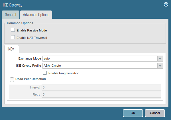
Click on Advanced Option, In IKEv1, select IKE Crypto Profile, which defines in Step 3.
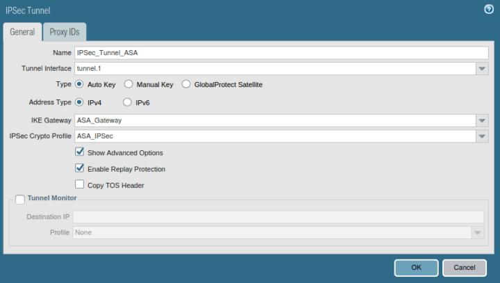
Creating the IPSec Tunnel
We have defined IKE Gateway and IPSec Crypto profile for our IPSec Tunnel. Now, we have to define the IPSec Tunnel. Go to Network >> IPSec Tunnels >> Add. Define the user-friendly name for IPSec Tunnel. Next, select the tunnel interface, which is defined in Step 2. Select the profiles for IKE Gateway and IPSec Crypto Profile, which are defined in Step 3 and Step 5 respectively.
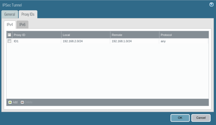
Go to the Proxy IDs Tab, and define Local and Remote Networks. In this scenario, I’m using 192.168.1.0/24 and 192.168.2.0/24 in LAN Networks.
Creating the Security Policy for IPSec Tunnel Traffic
Now, you need to create a security profile that allows the traffic from VPN Zone to Trust Zone. You need to Go Policies >> Security >> Add to define a new Policy.

Configuring Route for Peer end Private Network
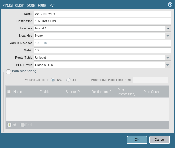
Now, you need to provide a static route for Peer end Private networks. Just go to Network >> Virtual Routers >> Default >> Static Routes >> Add. Select the Name for this Route and define the destination network for this route, i.e. 192.168.1.0/24 in this example. Select the Next Hop to Tunnel Interface which is defined in Step 2.
We finished the configuration of the IPSec tunnel in the Palo Alto firewall. Now, we will configure the IPSec tunnel in FortiGate Firewall.
Steps to configure IPSec Tunnel in Cisco ASA Firewall
Now, we will configure the IPSec Tunnel in Cisco ASA Firewall. Here, in this example, I’m using the Cisco ASA Software version 9.8(1). Although, the configuration of the IPSec tunnel is the same in other versions also.
We need to configure the following steps to configure IPSec on Cisco ASA:
- Configuring the Phase1 (IKEv1)
- Defining the Tunnel Group and Pre-Shared Key
- Configuring the Phase2 (IPSec)
- Configuring the Extended ACL and Crypto Map
So, let’s start the configuration by configuring Phase1 of Cisco ASA. Access the global configuration mode of Cisco ASA and start with the below commands:
Configuring the Phase1 (IKEv1) on Cisco ASA
[terminal]ciscoasa(config)# crypto ikev1 enable outside
ciscoasa(config)# crypto ikev1 policy 10
ciscoasa(config-ikev1-policy)# authentication pre-share
ciscoasa(config-ikev1-policy)# encryption 3des
ciscoasa(config-ikev1-policy)# hash md5
ciscoasa(config-ikev1-policy)# group 2
ciscoasa(config-ikev1-policy)# lifetime 7200[/terminal]
Now, let’s quickly understand the meaning of each command.
- Encryption: 3des (It is used to encrypt the Phase1 traffic).
- Hash: md5 ( md5 is a hashing algorithm. It authenticates our data using Hash)
- Group: 2 (Diffie Hellman Group 2)
- Authentication: In this example, we are using the pre-shared key as authentication)
- Lifetime: 7200 (86400 Default lifetime for the Phase1)
In the Cisco ASA, we need to enable the Crypto IKEv1 to the Internet-facing interface. So, we can do this using the below command:
[terminal]ciscoasa(config)# crypto ikev1 enable outside[/terminal]
Configuring the Tunnel Group and Pre-Shared Key on Cisco ASA
Now, we need to define the tunnel interface and the Pre-Shared Key. In this article, I’m using GNS3Network as a pre-shared key.
[terminal]ciscoasa(config)# tunnel-group 2.2.2.2 type ipsec-l2l
ciscoasa(config)# tunnel-group 2.2.2.2 ipsec-attributes
ciscoasa(config-tunnel-ipsec)# ikev1 pre-shared-key GNS3Network[/terminal]
Configuring the IPSec IKEv1 (Phase2)
Here, we need to define the Encryption and Authentication methods for IPSec Phase2.
[terminal]ciscoasa(config-ikev1-policy)#crypto ipsec ikev1 transform-set ESP-AES-SHA esp-3des esp-md5-hmac[/terminal]
[terminal]ciscoasa(config)# crypto ipsec security-association lifetime seconds 7200[/terminal]
Now, let’s quickly understand each command.
- ESP: ESP Stands for Encapsulating Security Payload and it’s an IPSec Protocol
- 3DES: 3DES is one of the Encryption Algorithm
- MD5: MD5 is a Hashing algorithm, which is used to maintain the data integrity
- 7200 Seconds: IPSec Phase2 Key lifetime
Configuring the Crypto MAP and Extended ACL to allows IPSec traffic on Cisco ASA
This is the final step of our configuration. Here, we need to define an Extended ACL to allow the traffic. Also, here we need to configure the Crypto MAP and call the configured crypto map to the External Interface. I am configuring two address objects to simplified the Access Control List (ACL).
Address Object and Extended ACL to allow traffic
[terminal]ciscoasa(config)#object-group network local-network
ciscoasa(config-network-object-group)#network-object 192.168.1.0 255.255.255.0
ciscoasa(config-network-object-group)#object-group network remote-network
ciscoasa(config-network-object-group)#network-object 192.168.2.0 255.255.255.0
ciscoasa(config-network-object-group)#access-list asa-paloalto-vpn extended permit ip object-group local-network object-group remote-network[/terminal]
Configuring the Crypto MAP
[terminal]ciscoasa(config)# crypto map outside_map 10 match address asa-paloalto-vpn
ciscoasa(config)# crypto map outside_map 10 set pfs group2
ciscoasa(config)# crypto map outside_map 10 set peer 2.2.2.2
ciscoasa(config)# crypto map outside_map 10 set ikev1 transform-set ESP-AES-SHA[/terminal]
Enabling the Crypto MAP on Outside Interface
[terminal]ciscoasa(config)# crypto map outside_map interface outside[/terminal]
Initiating the IPSec tunnel and verify the traffic using Wireshark
In this step, we just have to initiate the traffic on the IPSec tunnel. If both phases of the IPSec tunnel come up, then your configuration is perfect. So, let’s access the CLI of the Palo Alto Firewall and initiate the IPSec tunnel:
[terminal]admin@PA-VM>test vpn ipsec-sa[/terminal]
[terminal]admin@PA-VM>test vpn ipsec-sa[/terminal]
Now, let’s access Device >> IPSec Tunnels and check the status of the IPSec tunnel you just created! If both the phases tunnel is up, it will look like the below image:

Now, let’s initiate the traffic from one of the firewalls. I am initiating the traffic towards the Palo Alto Firewall from Cisco ASA.
[terminal]ciscoasa# ping inside 192.168.2.1
Type escape sequence to abort.
Sending 5, 100-byte ICMP Echos to 192.168.2.1, timeout is 2 seconds:
?!!!!
Success rate is 80 percent (4/5), round-trip min/avg/max = 30/30/30 ms[/terminal]
The first packet is dropped just because of the ARP request and response. No further packet will be dropped.
Optional: If you are tryining to initiate the traffic from Cisco ASA Interface IP [i.e. in this example], you need to allow the management access towards the subnet.
[terminal]ciscoasa(config)# management-access inside [/terminal]
Troubleshooting the IPSec tunnel – PA & ASA
In this part of this article, we will discuss some basic commands, which help you to troubleshoot the IPSec tunnel which is configured between the Cisco ASA and Cisco router.
Troubleshooting IPSec tunnel on the Cisco ASA Firewall
[terminal]ciscoasa# show running-config ipsec[/terminal]
[terminal]ciscoasa# show running-config crypto ikev1[/terminal]
[terminal]ciscoasa# show running-config crypto map[/terminal]
Troubleshooting IPSec tunnel on Palo Alto Firewall
Let’s access the Monitor >> System and use the filter “( subtype eq vpn )”. Here, you will find all VPN-related logs.
If you getting issue with the IPSec tunnel, you can use the following commands to initiate the IPSec tunnel:
[terminal]admin@PA-VM>test vpn ipsec-sa[/terminal]
[terminal]admin@PA-VM>test vpn ipsec-sa[/terminal]
Analyzing the IPSec traffic through the Wireshark
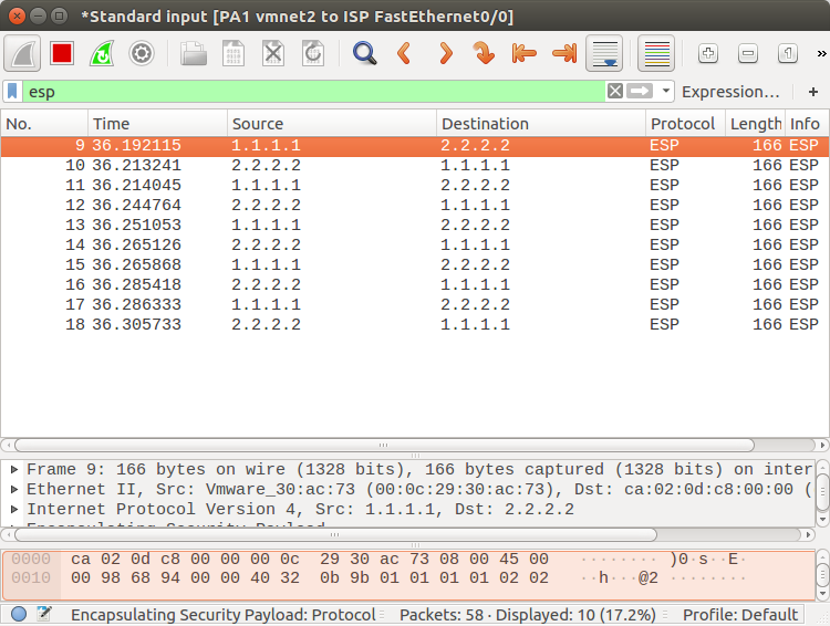
During the configuration of the IPSec tunnel, we defined ESP (Encapsulating Security Payload) as the IPsec protocol, so all the real traffic which goes towards the peer end will be encrypted using this protocol. So, you will only find ESP packets in the packet capture as shown below.
Related Articles
- How to configure IPSec VPN between Palo Alto and FortiGate Firewall
- IPSec Tunnel Between Cisco Routers | Site to Site VPN Between Cisco Routers
- IPSec Tunnel between Cisco ASA Firewall and Cisco Router
- How to configure GRE Tunnel between Cisco Routers
Reference
Summary
In this article, we configure the IPSec tunnel between the Cisco ASA Firewall and Palo Alto Next-Generation Firewall. We also discussed the Encryption and Authentication algorithms. However, you must need static routable IP addresses to configure the IPSec VPN between two remote networks.
Hope you like this article! Please let us know if you need further help regarding the IPSec tunnel.
Its not Device >> IPSec Tunnels, its Network >> IPSec Tunnels
Hello Manmeet, thanks for the information :), I’ve corrected this!
i tried the same on GNS3 but phase 1 is up but not phase 2
ciscoasa(config)# sh crypto isakmp sa
IKEv1 SAs:
Active SA: 1
Rekey SA: 0 (A tunnel will report 1 Active and 1 Rekey SA during rekey)
Total IKE SA: 1
1 IKE Peer: 192.168.100.30
Type : L2L Role : initiator
Rekey : no State : MM_ACTIVE
There are no IKEv2 SAs
ciscoasa(config)# sh crypto ipsec sa
ciscoasa(config)#
Hello Sudhakar,
Could you please check the logs on PA?
You may check the ikemgr.log using the below command in PA CLI:
less mp-log ikemgr.log